
Data Flow Diagram (DFD)
In a Nutshell
A Data Flow Diagram shows how data moves and transforms as it crosses process boundaries. Unlike an architecture diagram (which shows components and infrastructure), a DFD focuses on the data itself — where it enters the system, what processes act on it, where it's stored, and where it exits. It's the right diagram when the interesting part of your design is what happens to the data, not what servers run the code.
How It Actually Works
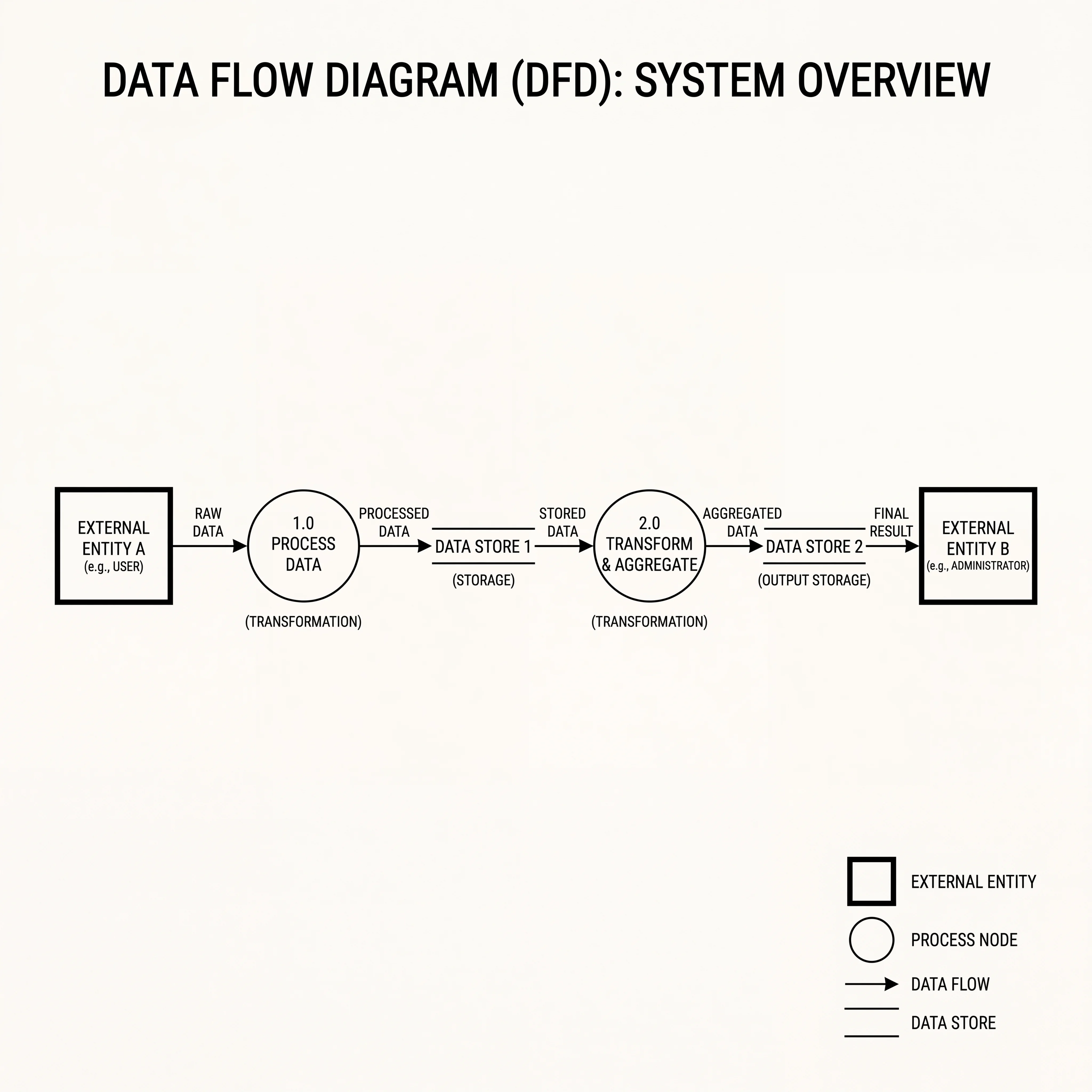
DFD Symbols
| Symbol | Shape | Meaning | Example |
|---|---|---|---|
| External Entity | Rectangle | A source or destination outside the system | User, Payment Gateway, Email Provider |
| Process | Circle or rounded rectangle | Something that transforms data | "Validate Order," "Calculate Price," "Generate Report" |
| Data Store | Open-ended rectangle (two horizontal lines) | Where data is persisted | Orders DB, User Cache, File Storage |
| Data Flow | Arrow with label | Data moving between elements | "order details," "payment token," "notification payload" |
Levels of DFD
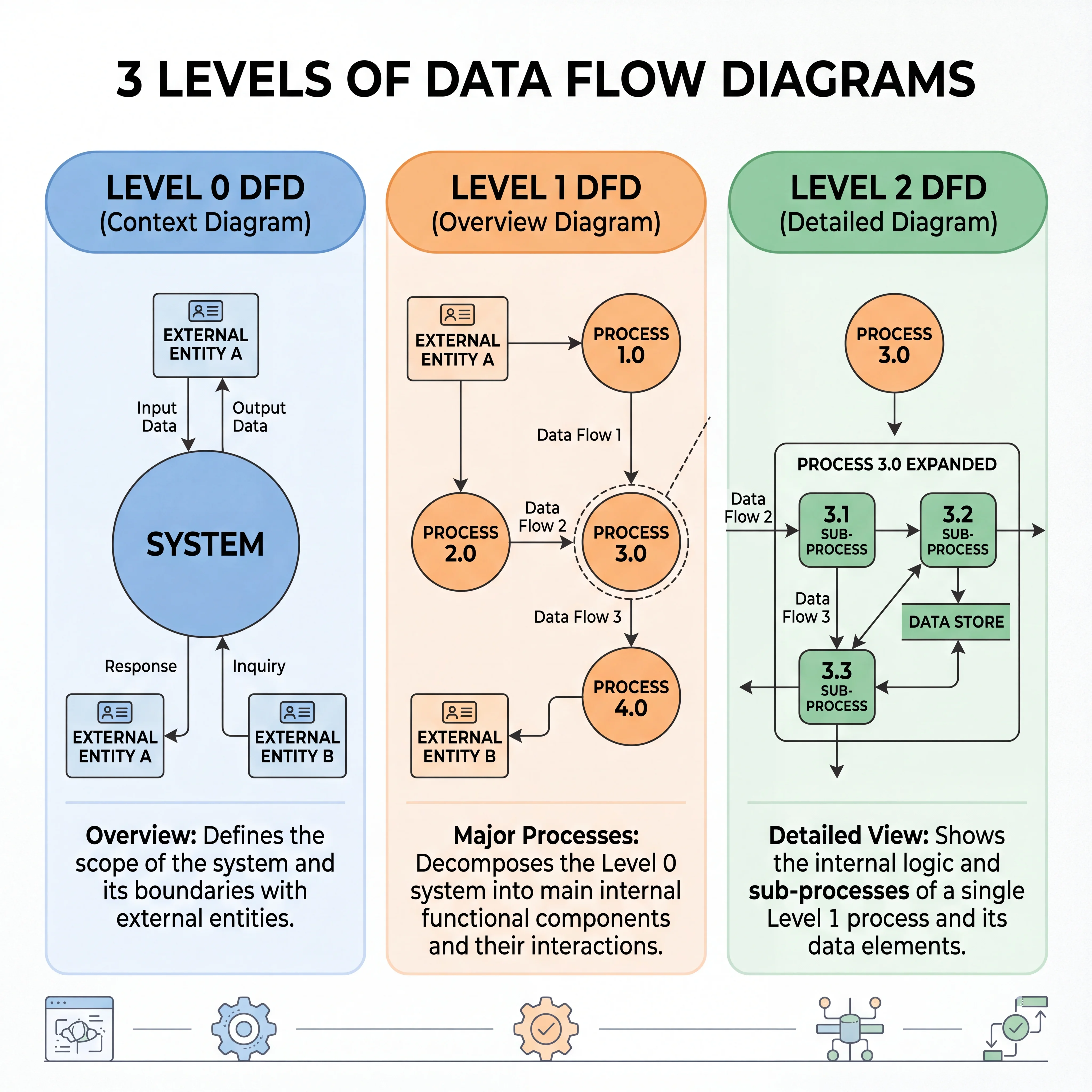
DFDs are drawn at increasing levels of detail:
Level 0 (Context Diagram): The entire system as a single process, showing only external entities and the data flows in/out. Answers: "What does this system interact with?"
Level 1: The single process from Level 0 is expanded into its major sub-processes. Answers: "What are the major steps inside the system?"
Level 2+: Each sub-process from Level 1 can be further decomposed. Rarely needed in interviews — Level 1 is usually sufficient.
When to Use a DFD vs Other Diagrams
| If the question is... | Use this diagram |
|---|---|
| What components exist and how are they connected? | Architecture diagram |
| How does data move and transform through the system? | DFD |
| What messages pass between actors, in what order? | Sequence diagram |
| What lifecycle does an entity go through? | State diagram |
DFDs are most valuable when:
- Data passes through multiple transformation stages (ETL pipelines, data processing)
- You need to show where data is stored at each stage
- Privacy/compliance is a concern — a DFD makes it clear which processes touch sensitive data
Seeing It in Action
Scenario: Level 1 DFD for an e-commerce checkout flow
┌──────────┐                                          ┌──────────────┐
│          │  cart items   ┌──────────────┐  valid     │              │
│  User    │──────────────▶│   Validate   │──order────▶│  Calculate   │
│(Customer)│               │    Order     │            │    Price     │
└──────────┘               └──────┬───────┘            └──────┬───────┘
                                  │                           │
                           invalid│                    total  │
                                  ▼                    amount │
                           ┌──────────────┐                   │
                           │ Return Error │                   ▼
                           │  to User     │            ┌──────────────┐
                           └──────────────┘            │   Process    │
                                                       │   Payment   │
┌──────────────┐  payment result                       └──────┬───────┘
│   Payment    │◀──────────────────────────────────────────────┘
│   Gateway    │                     │
└──────────────┘              payment │
                              status  │
                                      ▼
                               ┌──────────────┐  order record  ══════════
                               │    Create     │───────────────▶ Orders  ║
                               │    Order      │                ║  DB   ║
                               └──────┬────────┘                ══════════
                                      │
                               confirmation
                                      │
                                      ▼
                               ┌──────────────┐
                               │    Send      │
                               │ Confirmation │──email──▶ ┌────────────┐
                               └──────────────┘           │   Email    │
                                                          │  Provider  │
                                                          └────────────┘
What this reveals that an architecture diagram wouldn't:
- The exact data transformations: cart items → validated order → priced order → payment request → order record
- Where validation can fail and what happens (error returned to user)
- Which processes touch external systems (Payment Gateway, Email Provider)
- Where sensitive data (payment details) flows — important for PCI compliance
Interview Questions
Q: When would you choose a DFD over an architecture diagram to explain your design? Hint: When the interesting part is what happens to the data rather than what infrastructure runs the code. Data pipelines, ETL processes, checkout flows, and any system where data passes through multiple transformation stages benefit from a DFD.
Q: What's the difference between a Level 0 and Level 1 DFD? Hint: Level 0 (context diagram) shows the entire system as one process with external entities. Level 1 decomposes that single process into its major sub-processes. Level 0 answers "what does the system interact with?" Level 1 answers "what are the major steps inside?"
Q: How does a DFD help with security and compliance reviews? Hint: It makes data flows explicit — you can trace exactly which processes handle sensitive data (PII, payment info), where it's stored, and which external entities receive it. This is essential for GDPR data flow mapping, PCI-DSS scope determination, and threat modeling.
Q: Draw a Level 0 DFD for a ride-sharing application. What external entities would you include? Hint: External entities: Rider, Driver, Payment Gateway, Map/Routing Service, Notification Service. The system (one circle) receives ride requests from Rider, location updates from Driver, payment confirmations from Gateway, and sends notifications to both Rider and Driver.
Q: What are the limitations of DFDs? What can't they show? Hint: DFDs don't show timing or sequence (use sequence diagrams for that), control flow or conditions (use flowcharts), or state transitions (use state diagrams). They also don't show infrastructure details like load balancers or replicas. They're purely about data movement and transformation.
References
- Data Flow Diagrams — Lucidchart Guide — visual guide to DFD notation and levels
- Structured Analysis and System Specification by Tom DeMarco — the original text on DFDs in software engineering
- OWASP Threat Modeling — Data Flow Diagrams — using DFDs for security threat modeling
Dive Deeper
- Software Requirements by Karl Wiegers — Chapter on modeling data flows in requirements analysis
- Microsoft Threat Modeling Tool — uses DFDs as the basis for automated threat analysis
- GDPR Data Mapping with DFDs — ICO guide on using data flow analysis for compliance