
Use Case Diagram
In a Nutshell
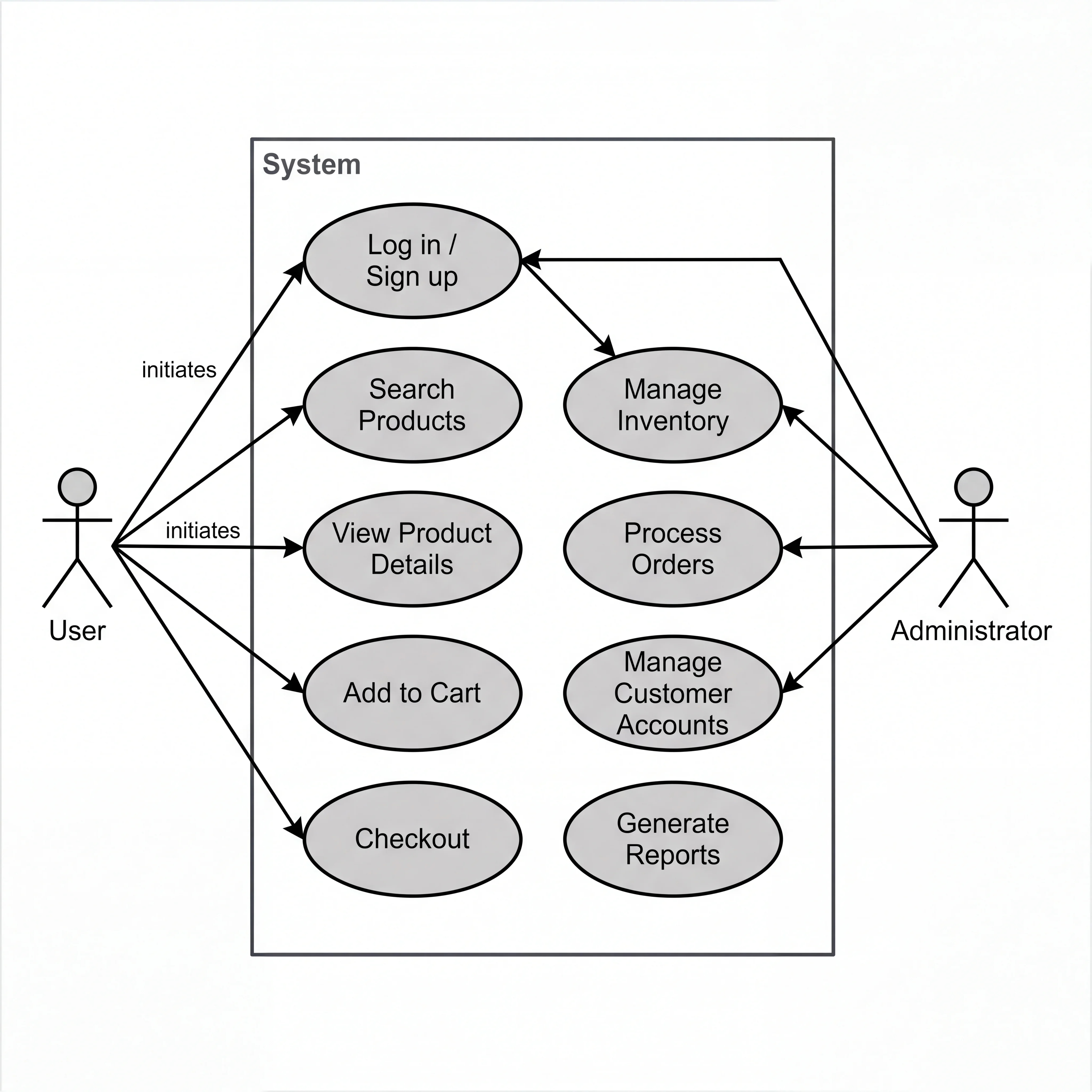
A use case diagram maps actors to the goals they can accomplish. It's the simplest UML diagram and the most useful for one specific purpose: confirming scope with a stakeholder. It answers: "Who uses this system, and what can they do?" You won't use it to design internals or show data flow — but before you start designing, it ensures everyone agrees on what "the system" includes and what it doesn't.
How It Actually Works
Notation
| Symbol | Meaning | Example |
|---|---|---|
| Actor | Stick figure (or labeled box for non-human actors) | Customer, Admin, Payment Gateway |
| Use Case | Oval with a verb phrase | "Place Order," "View Dashboard," "Generate Report" |
| System Boundary | Rectangle enclosing use cases | The scope of your system |
| Association | Line connecting actor to use case | Customer ── Place Order |
| Include | Dashed arrow with «include» | "Place Order" ──include──▶ "Validate Payment" (always happens) |
| Extend | Dashed arrow with «extend» | "Place Order" ◀──extend── "Apply Coupon" (optionally happens) |
| Generalization | Triangle arrow between actors | "Premium Customer" △── "Customer" (inherits all use cases) |
Include vs Extend
This is the most commonly confused part:
- «include» = the base use case always triggers the included use case. "Place Order" always includes "Validate Payment." It's a mandatory sub-step.
- «extend» = the extending use case sometimes adds behavior to the base. "Apply Coupon" extends "Place Order" but only when the user has a coupon. It's an optional add-on.
When to Use It
- Kickoff meetings — to align stakeholders on what the system does and who uses it
- Scope confirmation — in interviews, to quickly show you understand the actors and their capabilities
- Requirements traceability — each use case maps to one or more functional requirements
- Test planning — each use case becomes a test scenario
When NOT to Use It
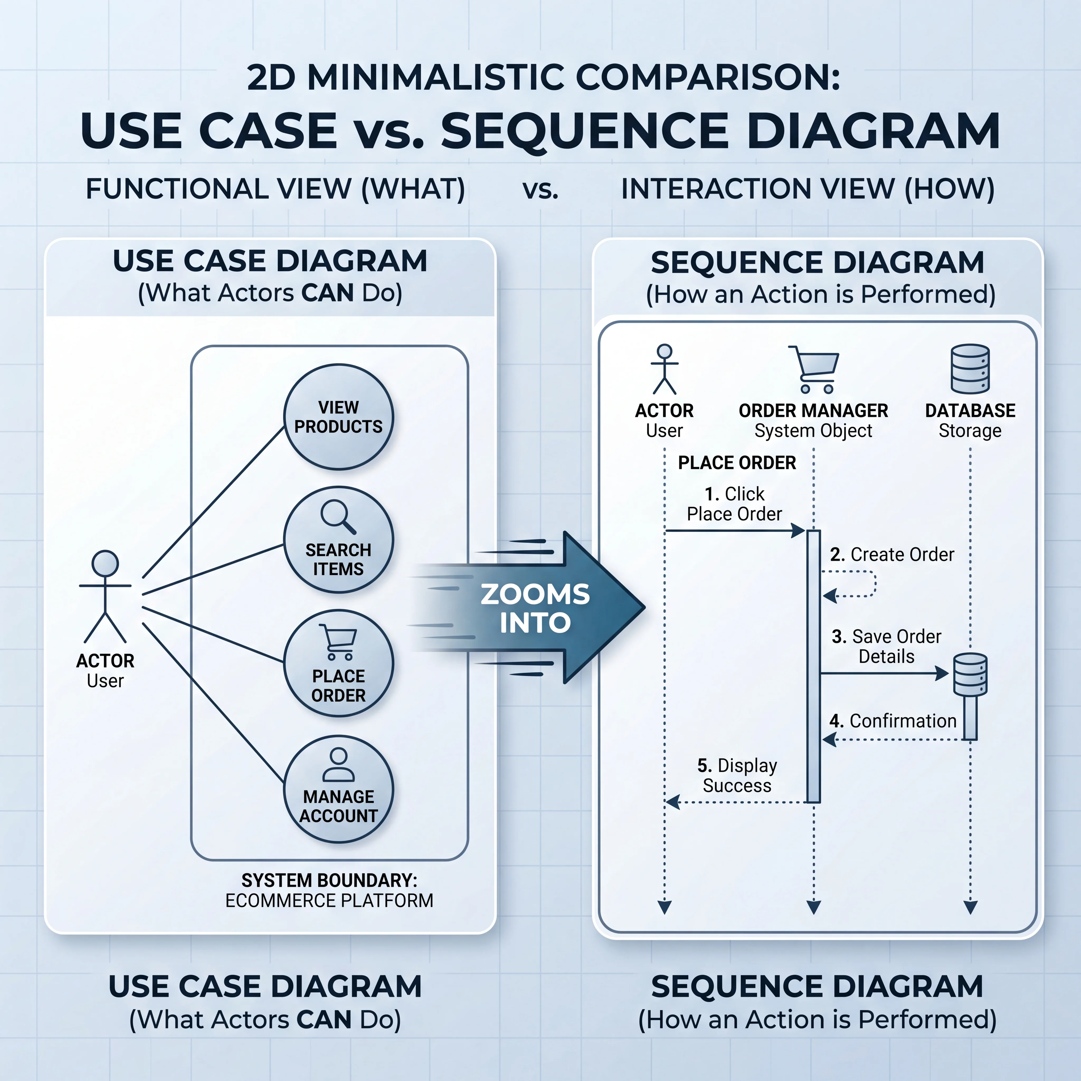
- For showing how something works (use sequence diagrams)
- For showing data or state (use DFDs or state diagrams)
- For detailed design (use class or component diagrams)
- For showing infrastructure (use architecture diagrams)
Seeing It in Action
Scenario: Use case diagram for an online banking system
                    ┌─────────────────────────────────────────┐
                    │          Online Banking System           │
                    │                                         │
 ┌──────┐          │   ┌─────────────────────┐              │
 │      │          │   │   View Account      │              │
 │      │──────────┼──▶│   Balance           │              │
 │      │          │   └─────────────────────┘              │
 │      │          │                                         │
 │      │          │   ┌─────────────────────┐              │
 │Customer│────────┼──▶│   Transfer Funds     │──include──▶ ┌──────────────┐
 │      │          │   └─────────────────────┘              │  Authenticate │
 │      │          │            ◀──extend──  ┌──────────┐   │    User      │
 │      │          │                         │ Schedule  │   └──────────────┘
 │      │          │                         │ Recurring │          ▲
 │      │          │                         └──────────┘          │
 │      │          │   ┌─────────────────────┐              include│
 │      │──────────┼──▶│   Pay Bills          │──────────────────┘
 │      │          │   └─────────────────────┘              │
 └──────┘          │                                         │
                    │   ┌─────────────────────┐              │
      ┌──────┐     │   │   Manage Users       │              │
      │      │     │   └─────────────────────┘              │
      │ Admin │────┼──▶                                      │
      │      │     │   ┌─────────────────────┐              │
      │      │─────┼──▶│   Generate Reports   │              │
      └──────┘     │   └─────────────────────┘              │
                    │                                         │
                    │   ┌─────────────────────┐    ┌────────┐│
                    │   │   Process Payments   │◀───│External││
                    │   └─────────────────────┘    │Payment ││
                    │                               │Gateway ││
                    │                               └────────┘│
                    └─────────────────────────────────────────┘
What this reveals:
- Two human actors (Customer, Admin) with different capabilities — scope is clear
- One system actor (Payment Gateway) — external dependency identified
- «include»: Both "Transfer Funds" and "Pay Bills" always require authentication
- «extend»: "Schedule Recurring" is optional behavior that extends "Transfer Funds"
- System boundary makes explicit: user management and reports are Admin-only features
Interview Questions
Q: When would you draw a use case diagram in a system design interview? Hint: In the first 2–3 minutes, to quickly confirm scope. "Here are the actors and what they can do — does this match the requirements?" It's a 30-second sketch, not a detailed exercise. Then move on to architecture.
Q: What's the difference between «include» and «extend»? Give examples for a food delivery app. Hint: Include: "Place Order" always includes "Process Payment" (can't order without paying). Extend: "Place Order" is optionally extended by "Apply Promo Code" (only when user has one). Include = mandatory sub-step. Extend = optional add-on.
Q: How do you handle different user roles in a use case diagram? Hint: Use actor generalization. "Premium Customer" inherits all use cases from "Customer" and adds new ones (e.g., "Access Priority Support"). This is shown with a triangle arrow from the specialized actor to the general actor.
Q: Can a use case diagram show non-functional requirements? Hint: Not directly — use case diagrams are purely functional (what actors can do). Non-functional requirements (latency, availability, security) are documented separately. However, you can annotate use cases with NFR notes (e.g., "Transfer Funds — must complete in < 3 seconds").
Q: You're designing a system with 30 use cases. How do you keep the diagram manageable? Hint: Group related use cases into packages or sub-systems (e.g., "Account Management," "Transactions," "Reporting"). Draw a high-level diagram showing packages, then detailed diagrams for each package. No single diagram should have more than 10–12 use cases.
References
- UML Use Case Diagram — Visual Paradigm — notation and examples
- Writing Effective Use Cases by Alistair Cockburn — the definitive guide to use cases
- UML Distilled by Martin Fowler — practical guide to use case diagrams
Dive Deeper
- Use Cases and User Stories — What's the Difference? — Mike Cohn on when each is appropriate
- User Story Mapping by Jeff Patton — modern alternative to use case diagrams for product planning
- PlantUML Use Case Diagram — draw use case diagrams as code